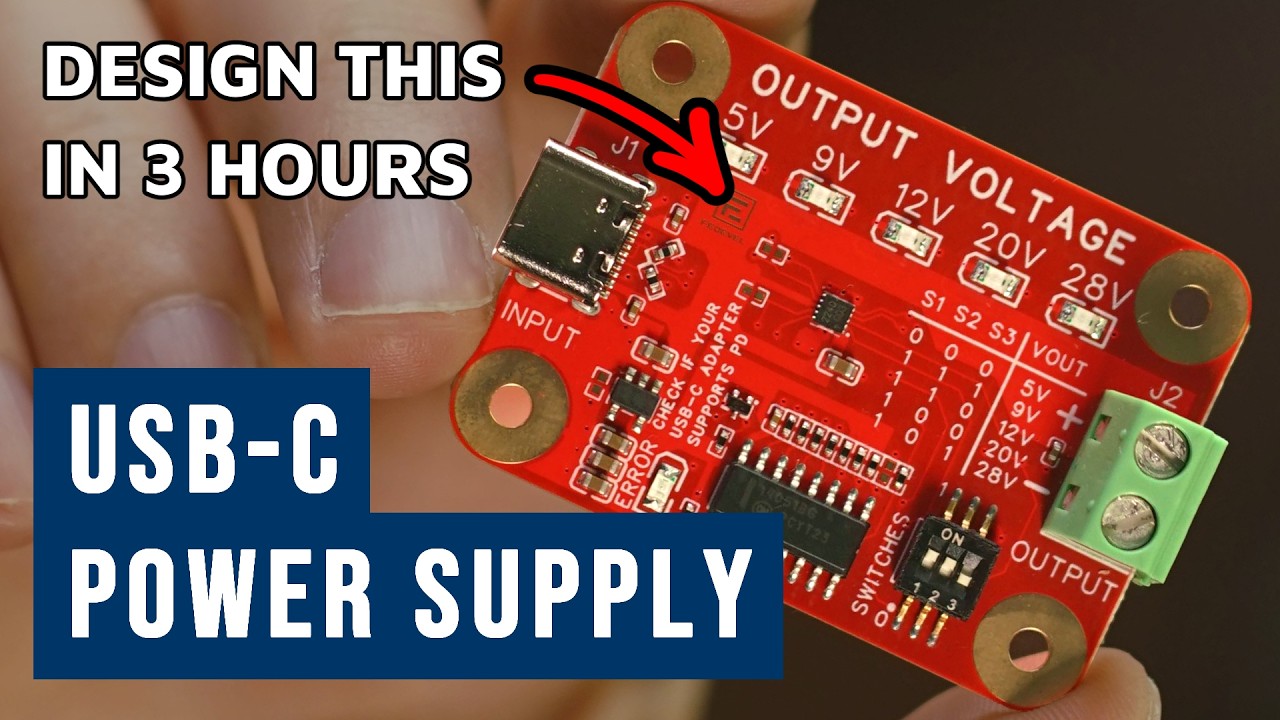
How to Design a USB-C Power Supply (5V–28V) in 3 Hours | Full Tutorial | EasyEDA
You will learn how to draw schematic, do PCB layout and manufacture your board. You will design an useful USB-C PD Power supply based on CH224A / CH224Q chip.
Chapters:
- 00:00What you will design in this tutorial
- 00:56Starting a new project
- 03:34Adding CH224A
- 05:06Updating Schematic symbol
- 08:25Adding 1uF Capacitor
- 11:36Adding USB-C Connector
- 15:41Adding USB Protection
- 18:05Adding 100nF
- 19:40Adding 1k Resistor
- 20:46Marking component NF (Not Fitted)
- 23:20Adding 10k Resistor
- 25:40Adding 6.8k Resistor
- 28:10Adding 100k Resistor
- 29:54Adding Switches
- 36:46Adding 3.3V LDO
- 43:15Adding Error LED
- 44:47Adding MOSFET Transistor 2N7002
- 46:11Adding Output Connector
- 49:28Adding Voltage LED Indicators
- 52:36Adding Multiplexer MC14051B
- 59:41Adding I2C Header
- 01:02:27Creating your own component - Mounting Holes
- 01:06:31Annotating Schematic
- 01:07:51Running DRC Check
- 01:08:05Importing Schematic to PCB
- 01:08:49Adding Board Outline
- 01:09:43Placing components
- 01:23:11Setting up PCB Design Rules
- 01:24:27Setting up Stackup (4 Layer PCB)
- 01:25:04PCB Layout
- 01:51:14Swapping pins in PCB
- 01:53:13Routing USB and Calculating Impedance
- 01:58:56Running DRC Check
- 02:00:51Replacing CH224A for CH224Q
- 02:12:11Adding Copper Pours
- 02:18:16Copper Region Priority
- 02:20:15Updating track width to 50 OHM impedance
- 02:21:16Adjusting Silkscreen - TOP
- 02:32:59Adjusting Silkscreen - BOTTOM
- 02:38:15Adding LOGO
- 02:39:15Adding GOLD LOGO
- 02:41:01Adjusting GND under Exposed Pad
- 02:44:11Generating Outputs for Manufacturing
- 02:45:14Generating and checking Gerber files
- 02:48:11Generating BOM (Bill of Material)
- 02:49:17Generating Pick & Place file
- 02:50:39Ordering PCB and Assembly
- 02:57:30Finished boards
- 02:59:10Testing our Board
- 03:01:07Testing I2C and Any Output Voltage
- 03:05:49Where to find and download the project files
- 03:07:06Thank you very much for watching