8 Steps to Bring up your Board to Life
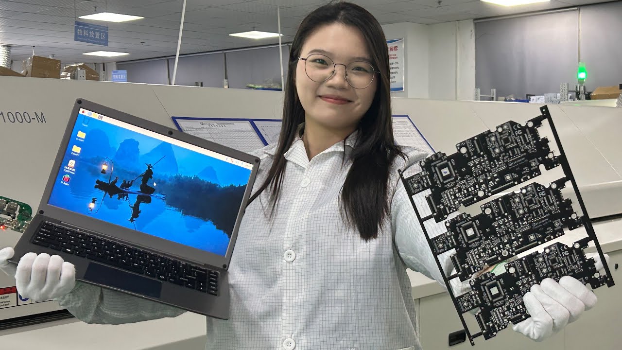
This is a real video, from bringing up iMX6 Rex board to Life.
Step 1: Visual inspection
What to look for:- if all the the components for your VARIANT are correctly fitted,
- if all the pin 1 are placed correctly,
- if there are no visible short circuits between pads,
- if pads are soldered with a good quality (QFN pads, connectors with a small pitch… )
Tip: Print out Assembly drawing with all the components and testpoints
Step 2: Measure impedance on power rails
Go through all the power rails and measure impedance between 0R and a power rail. There must not be 0 OHM – that would be a short circuit.Tip: Some power rails may have very low impedance e.g. CPU core voltage, memories, …. 20OHMs, 40OHMs, 90OHMs … don’t be surprised.
Step 3: Connect power supply for the very first time
- double check voltage output from your power supply (output level +5V, +12V, +24V, ….)
- set your power supply current limit (always use power supply with limiting current e.g. 1A, 1.5A, …)
- double check, if you have connected your board correctly (polarity + / -)
- cover the board (in case something blow up e.g. if a capacitor is soldered the wrong way, it may very easily happen)
- switch on the power
- watch the maximum current, watch if current is changing or is stable (e.g. if it goes rappidly up, something may be wrong)
- check component temperature with your finger (touch first all the integrated circuits, but try also passive components e.g. resistors, inductors and beads). Nothing should get very hot – if CPU goes very hot, use heatsink.
Tip: Print out Assembly drawing with all the components and testpoints
Step 4: Measure all the on board voltages
In this step check all the power rails.Tip: Many times, you set output voltage through a resistor divider, so it’s very important you know you didnt make any mistake in calculation and all to powers are in tollerance.
Step 5: Measure crystals and oscillators
It’s very important you check all the crystals & oscillators. It may really happen, that some of the crystals may not start and board will not boot up.Step 6: Upload firmware
We used Freescale MfgTool. If everything is working ok, after you connect your i.MX6 board to your PC (via USB), you will see a new USB device: HID-compliant device (USB input). Press “Start” to upload firmware into your board (you may want to check, what profile is used and what firmware will be uploaded). Watch the information about board current consumption. If everything goes ok, once the board starts booting, you will see the current fluctuation.Step 7: Check Serial TX signal
Many times happen, that the RS232 cable that you use to connect your board with your PC is wrong (e.g. doesnt cross RX / TX signals correctly). It’s very good practise to measure TX activity directly on your CPU output. Connect an oscilloscope and when boards is booting, you will see some activity on the signal.Step 8: Connect Console
This is the moment of the truth. If everything is ok, you will see console output coTip: Very often, the default console settings are Baud rate: 115200 / Data: 8b / Parity: None / Stop: 1b / Flow control: None
Tip: Mark each board with a sticker and a number
Use a sticker and write down board number, so you can easily identify the boards. Keep making notes about each board in a document or on a paper (e.g. if you see something unusual about the board – write it down, something doesn’t work – write it down, …).Note: Some boards will come with a serial number sticker from production, so you don’t have to do this step.
For the very first testing, use the board which looks the best e.g. best soldered and everything looks ok.
Links:


