x86 Hardware design – What everyone should know
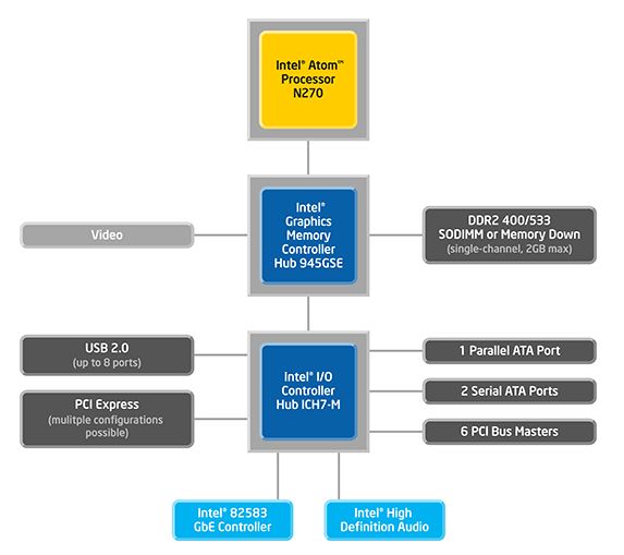
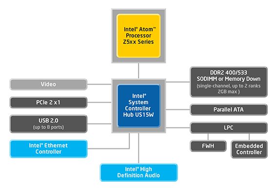
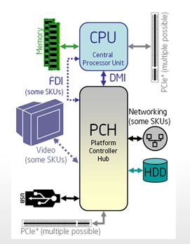
The x86 use often three chip solution, but it’s not a rule. Mobile platforms many time use only two chips. The chips used to be known as CPU (to support different CPU speeds and models), North Bridge (mostly memory interface + graphic interface or graphics), South Bridge (peripherals). These days manufacturers use different names such GMCH, SCH, PCH, …
Picture: Intel N270 (Three chips) / Intel ATOM Z5xx / Intel CORE i7
Picture: Intel N270 (Three chips) / Intel ATOM Z5xx / Intel CORE i7
Power sequencing
x86 boards support several power states. The most well know are:
More about power states: see ACPI specification
Power sequencing is controlled by South Bridge. Mobile platforms use a Embedded controller instead. The embedded controller integrates often also other features – keyboard interface, volume control, ambient light sensor for automatic display backlight control, …
x86 boards support several power states. The most well know are:
- S0 – Board is ON
- S3 – Board is in Sleep (when you close your laptop, without shutting down)
- S5 – Board is OFF, but can be switched pressing Power button
- G3 – Disconnected from Main power
More about power states: see ACPI specification
Power sequencing is controlled by South Bridge. Mobile platforms use a Embedded controller instead. The embedded controller integrates often also other features – keyboard interface, volume control, ambient light sensor for automatic display backlight control, …
High Currents & High Heat
When designing a x86 board, it’s important to know how a lot of heat will be taken away. Power supplies are designed to support currents up to tens of Amps. PCB layout has to take this into consideration and wide tracks / planes + multiple VIAs are required for power tracks.
When designing a x86 board, it’s important to know how a lot of heat will be taken away. Power supplies are designed to support currents up to tens of Amps. PCB layout has to take this into consideration and wide tracks / planes + multiple VIAs are required for power tracks.
BIOS
BIOS development is one of the key parts of x86 board development. It’s done by BIOS companies (Phoenix (Award), Insyde, … ) or by BIOS developers (they own a licence to source code of BIOS). Basic BIOS binaries are provided together with development platform, but must be customized based on the new board design. BIOS customization may easily cost around $900 per day.
Manufacturers of peripheral chips provide binaries for BIOS e.g Video BIOS, Ethernet BIOS (to support booting over Ethernet …), SATA BIOS (to support RAIDS …).
Open source BIOSes are also available – for example Coreboot (formerly known as LinuxBIOS)
A replacement for the older BIOS has been developed. The replacemnt is known as UEFI and is supported by several big manufacturers such Intel, AMD, IBM …
Booting
Initially, BIOS is executed directly from BIOS FLASH memory. Once system memory has been initialized (together with some other code), the BIOS starts running from DDR.
Initially, BIOS is executed directly from BIOS FLASH memory. Once system memory has been initialized (together with some other code), the BIOS starts running from DDR.
BIOS Debugging
Before video interface is initialized, a serial console or JTAG can be used to debug BIOS. Standard BIOS diagnostic output is called POST code. This code differentiate between manufacturers. BIOS POST code is a two/four digits hex value written by BIOS software on port 0x80. For easier diagnostic, this code can be read by POST code diagnostic cards.
Do you have any questions or you think something else is also important? Leave a comment.


